
Dynamics - Key Concepts 3


Impulse and 

Momentum


In classical mechanics, an impulse is defined as the integral of a force with respect to time. When a force is applied to a rigid body it changes the momentum of that body. A small force applied for a long time can produce the same momentum change as a large force applied briefly, because it is the product of the force and the time for which it is applied that is important. 
The impulse is equal to the change of momentum.
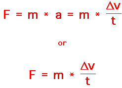
If both sides of the above equation are multiplied by the quantity t, a new equation results.


The quantity(Force X time) is known as impulse


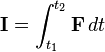
Impulse I produced from time t1 to t2 is defined to be

\mathbf{I} = \int_{t_1}^{t_2} \mathbf{F}\, dt
where F is the force applied from t1 to t2.

Momentum can be defined as "mass in motion." In terms of an equation, the momentum of an object is equal to the mass of the object times the velocity of the object.

Momentum = mass x velocity

   = m x v

where m is the mass and v is the velocity.
And  the quantity mXv is called  the momentum,If initial velocity of the particle is V1 and final velocity is V2 ,then the quantity mXΔv must be the 
change in momentum.

change in momentum (mXΔv) = Final momentum - Initial momentum
 m( v2-v1) = mv2 - mv1
The equation really says that the

Impulse = Change in momentum

\mathbf{I} = \int_{t_1}^{t_2} \mathbf{F}\, dt    =    
mv2 - mv1


Momentum Conservation Principle :


If the sum of Impulses due to external forces is zero the momentum of the system remains constant or conserved.


mv2 - mv1 = 0


mv1 = mv2 = mv3 .........mv= constant

Comments

Popular posts from this blog

Relation between Modulus of Elasticity and Modulus of Rigidity

Modulus of Elasticity (E)   It is the ratio between Normal stress to Normal strain within the elastic limit. Elastic Modulus E = Normal stress/Normal strain E =  s/e Modulus of Rigidity (G)  It is the ratio between Shear stress to Shear strain within the elastic limit. Rigidity Modulus G = Shear stress/ Shear strain G =    Ƭ / ø   Relation between Modulus of Elasticity and Modulus of Rigidity: Consider a solid cube  PQRS is  subjected to a shearing force F.  Let  Ƭ     be the shear stress produced in the faces PQ and RS due to this shear force. The complementary shear stress consequently produced in the vertical faces PS and RQ is also equal to same and shown in figure as Ƭ   Due to the pure shearing force, the cube is deformed PQRS to PQR'S' . The point   S moved to S' and point R moved to R' as shown in fig.  The shear strain = The angle of distortion  ø                          ø = RR'/ RQ ---(1) Shear strain = Shear stress /Rigidity modulus                

PORTAL METHOD and CANTILEVER METHOD

The behavior of a structure subjected to horizontal forces depends on its height to width ratio. The deformation in low-rise structures, where the height is smaller than its width, is characterized predominantly by shear deformations. In high rise building, where height is several times greater than its lateral dimensions, is dominated by bending action. To analyze the structures subjected to horizontal loading we have two methods. Portal method  and Cantilever method 1. PORTAL METHOD The portal method is an approximate analysis used for analysing building frames subjected to lateral loads such as Wind loads/ seismic forces.  Since shear deformations are dominant in low rise structures, the method makes simplifying assumptions regarding horizontal shear in columns.  Each bay of a structure is treated as a portal frame, and horizontal force is distributed equally among them. Assumptions in portal method   1. The points of inflection are located at the mid-height of each column above th

Shearing Stresses Distribution in Circular Section

Show that the shearing stress developed at the neutral axis of a beam with circular cross section is  τ max = (4/3)(F/πr2). Assume that the shearing stress is uniformly distributed across the neutral axis.  Solution : Let us consider the circular section of a beam as displayed in following figure. We have assumed one layer EF at a distance y1 from the neutral axis of the circular section of the beam Shear stress at a section will be given by following formula as mentioned here Where, F = Shear force (N) τ = Shear stress (N/mm2) A = Area of section, where shear stress is to be determined (mm2) ȳ = Distance of C.G of the area, where shear stress is to be determined, from neutral axis of the beam section (m) Q = A. ȳ = Moment of the whole shaded area about the neutral axis I = Moment of inertia of the given section about the neutral axis (mm4) For circular cross-section, Moment of inertia, I = ПR4/4 b = Width of the given section where shear stress is to be determined. Let us consider on