Shear stress distribution for Tee section.
T - section is not symmetrical over neutral axis, shear stress distribution also will not be symmetrical. The method of finding shear stress distribution in t section is explained in the following example.
Example
1. A T-section contains a flange of size 150 mm × 50 mm and web of size 50 mm × 150 mm. This section is subjected to a vertical shear force of 100 kN. Determine the maximum shear stress and draw the shear stress distribution diagram along with values at vital points.
Centroid of section is 125 mm from the bottom face and moment of inertia around the centroidal axis is I = 5312.5 × 104 mm4.
Solution
The Shear stress at a layer is
τy = Vxay'/ Ib = VxQ/ Ib
Where
a = Area between the extreme face of beam and the plane at which the shear stress is τy
y' = Distance of the centroid of area ‘a’ from N.A
Q = a.y' = the first moment of an area of the shaded section about N.A.
Vx = Shear force at the cross-section= 100 kN
I = Moment of Inertia of the beam cross section about N.A.
b = Width of the fiber at the shear plane
Therefore, The Shear stress at a neutral layer is
τmax = Vxay'/ Ib = VxQ/ Ib
The first moment of the area of the section above the NA about the NA is = ay' Q =[(150 × 50) × 50 + (50 × 25) × 12.5] =390625
b= 50mm, I = 5312.5×104 mm4
τmax = (100×1000x390625) / (5312.5×104×50)
= 14.71 N/mm2
In the flange shear stress at the just above junction of flange and web,The first moment of the area of the flange about the NA is = ay'= Q =150x50x50 =375000
b= 150mm, I = 5312.5×104 mm4
τfw= (100×1000x375000)/(5312.5×104 ×150)
τfw= (100×1000x375000)/(5312.5×104 ×150)
= 4.71 N/mm2
In the web shear stress at the just below the junction of flange and web,
In the web shear stress at the just below the junction of flange and web,
Q =150x50x50 =375000
b= 50mm, I = 5312.5×104 mm4
τwf= (100×1000x375000)/(5312.5×104×50) = 14.12 N/mm2
The shear stress distribution is shown in Figure.

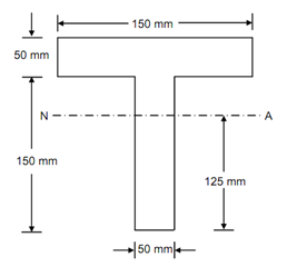
2. A simply supported T beam of length L carries a concentrated load P as shown in fig. Find: (a) The maximum shear stress, the shear flow qj, and the shear stress Tj in the joint between the flange and the web; (b) the maximum bending stress.
Given: P = 5 kN and L = 4 m.
Solution:
For given load and span , we draw the shear force and bending moment diagrams.

The maximum shear force Vx equals 2.5 kN on all cross sections of the beam and the maximum bending moment M is 5 kN-m
The shape of the beam is T- section as shown in fig.

We required to find the position of centroid and moment of Inertia of the section about its centroidal axis.
The distance of centroid form bottom of the section =

The moment of inertia I about the NA is determined by the parallel axis theorem:

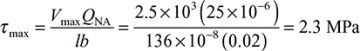
The maximum shearing stress in the beam takes place at the NA on the cross section supporting the largest shear force Vmax= 2.5 kN
The first moment of the area of the section above the NA, about the NA is
QNA = 50(20)25 = 25×103 mm3= 25x10-6 m3
b = 20mm = 0.02 m
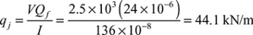
and the shear stress at junction τj
τj = qj/b = 44.1/0.02 = 2.205 MPa.
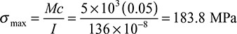
The Maximum Bending stress:
The maximun bending moment takes place at midspan of the beam is M = 5 kN-m
The maximum fiber distance from N.A is
C = 50mm
The maximum bending stress =
Assignment :
1. The T section shown in Fig. is the cross-section of a beam formed by joining two rectangular pieces of wood together. The beam is subjected to a maximum shearing force of 60 kN. Show that the NA is 34 mm from the top and the moment of inertia about NA is I = 10.57×106 mm4. Using these values, determine the shearing stress (a) at the neutral axis and (b) at the junction between the two pieces of wood.

Comments
Post a Comment