In Engineering Mechanics the study of the causes of motion and changes in motion is called as Dynamics.
For convenience, dynamics is divided into two branches, Kinematics and Kinetics.
Kinematics :It is the branch of classical mechanics that describes the motion of bodies (objects) and systems (groups of objects) without consideration of the forces that cause the motion.
Kinetics:It is the branch of classical mechanics that describes the motion of bodies (objects) and systems (groups of objects) by consideration of the forces that cause the motion.
Types of Motion:
Translatory motion:
In translatory motion the particle moves from one point in space to another. This motion may be along a straight line or along a curved path.
Motion of a particle along a straight line is called Rectilinear motion and
Motion along a curved path is called Curvilinear motion.
 |
| Curvilinear motion: A car moving on a curved road. |
 |
| Rectilinear motion : A car moving in a straight road |
Rotatory motion:
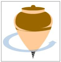
In rotatory motion the particles of the body describe concentric circles about the axis of motion.
In rotatory motion the particles of the body describe concentric circles about the axis of motion.
 |
| Rotatory motion: rotating Top |
Vibratory motion:
In vibratory motion the particles move to and fro about a fixed point.
Distance and displacement are two quantities that may seem to mean the same thing yet have distinctly different definitions and meanings.
Displacement is a vector quantity, that refers to the object's overall change in position.Displacement is a measurement of change in position of the particle in motion. Its magnitude and direction are measured by the length and direction of the straight line joining initial and final positions of the particle. Obviously, the length of the straight line between the positions is the shortest distance between the points.
Distance is a scalar quantity that refers to "how much ground an object has covered" during its motion.
Speed and Velocity:
Speed is the rate of change of distance with time, and Velocity is the rate of change of displacement with time.Speed is the first derivative of distance with respect to time,and Velocity is the first derivative of displacement with respect to time.
The average speed during the course of a motion is often computed using the following formula:
In contrast, the average velocity is often computed using this formula
Acceleration:
It is the rate of change of velocity with respect to time.
The term acceleration is used in general for an increase the magnitude of velocity wiht respect to time. a decrease in velocity is called deceleration.
Acceleration shows the change in velocity in a unit time. Velocity is measured in meters per second, m/s, so acceleration is measured in (m/s)/s, or m/s2, which can be both positive and negative.
Uniform acceleration
Uniform or constant acceleration is a type of motion in which the velocity of an object changes by an equal amount in every equal time period.
simple formulae that relate the following quantities: displacement, initial velocity, final velocity, acceleration, and time:
where
 = displacement
 = initial velocity
 = final velocity
 = uniform acceleration
- t = time.
-
- Motion with Variable acceleration
- The equations derived for uniformly accelerated motion are not applicable to the motion with variable acceleration.
- The relation between,
- displacement, initial velocity, final velocity, acceleration, and time are,
- What is the velocity at t = 0 ?
- When does velocity become zero?
- What is the velocity at the origin ?
Instantaneous velocity Instantaneous acceleration
 a = v. dv/dxRelation between acceleration and velocity
 Kinematic equation for motion
 when one or more of the above quantities are specified, the other can be obtained by process of differentiation or integration, using the above relationships.In problems requiring integration, the constants of integrations can be determined from specified conditions of motion.
EXAMPLE
:If the position of a particle along x – axis varies in time as :x=2t2−3t+1 Then :Solution :We first need to find out an expression for velocity by differentiating the given function of position with respect to time as :v=đđt(2t2−3t+1)=4t−3 (i) The velocity at t = 0,v=4x0−3=−3m/s (ii) When velocity becomes zero :For v = 0,4t−3=0⇒t=34=0.75 s. (iii) The velocity at the origin :At origin, x = 0,x=2t2−3t+1=0⇒2t2−2t−t+1=0⇒2t(t−1)−(t−1)=0⇒t=0.5 s, 1 s. This means that particle is twice at the origin at t = 0.5 s and t = 1 s. Now,v(t=0.5 s)=4t-3=4x0.5−3=-1 m/s. Negative sign indicates that velocity is directed in the negative x – direction.v(t=1 s)=4t-3=4x1−3=1 m/s.


Comments
Post a Comment