Principal Plane and Principal StressIt is the Plane in which only normal stress is acting without Shear Stresses is called principal plane.The normal stresses which are acting on Principal Plane are called as Principal Stress. Sign Conventions: 1.Tensile normal stress is considered as positive and compressive normal stress is considered as negative.
2. Shear stress acting on a face is considered positive if it rotate the element in clockwise direction and negative if in anticlockwise direction.
Stresses on Oblique Plane
The normal stresses (sx and sy) and the shear stress (txy) are acting vary smoothly on a body, the normal and tangential stresses or shear stress acting on a Oblique plane making a rotation of an angle q to the vertical face are given by,

sq = (sx+sy)/2 + {(sx-sy)/2}cos2q + txy sin2q -- (1)
tq = {(sx-sy)/2} sin2q - txy cos2q - (2)
In above equations, there exist a couple of particular angles where the stresses take on special values.
First, there exists an angle qp witch is called principal plane , here the shear stress txy becomes zero.
That angle qp is found by setting txy to zero in the above shear transformation equation. The result is, the principal planes are located at
 ----(3) ----(3)
This equation will express in a triangle and calculate cos2q , Sin2q

by substitute the cos2q , Sin2q in stress transformation equation (1) and principal stresses are found from the original stresses (expressed in the x,y directions) via,
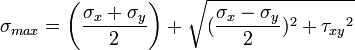
The Maximum and Minimum principal stresses are 
We can express principal stresses in single equation -
 --(4) --(4)
solving the above equation(3) for qp we have a set of two values for qp The angle qp defines the principal directions where the only stresses are normal stresses. These stresses are called principal stresses.
These two values will be separated by 90 degree (or, 2qp will be separated by 180 degree). One angle will correspond to the maximum normal stress,and the other will correspond to the minimum normal stress.
The transformation to the principal directions can be illustrated as shown in a figure.
 |
|
| Another important angle, qs, is where the maximum shear stress occurs. This is found by finding the maximum shear stress by differentiate the shear transformation equation and equate to zero. The result is, 
By substituting (cos2q , Sin2q) in shear stress transformation equation (2),The maximum shear stresses are found from the original stresses (expressed in the x,y directions).
Maximum Shear stress ( max) on plane is given by

t max = (s1 - s2) / 2
The maximum shear stress is equal to one-half the difference between the two principal stresses,
The maximum shear stress plane qs is 45 degrees from principal plane qp.
The transformation to the maximum shear stress direction can be illustrated as:
qs = qp + 45
 |
Transformation of stresses in two dimensions,showing the planes of action of principal stresses, and maximum and minimum shear stresses are shown in the above figure.

a)The principle stresses are given by the formula
Example:
For a given loading conditions the state of stress in the wall of a cylinder is subjected to normal stresses 85 MN/m2 tensile,in x- direction and 25 MN/m2 tensile in y- direction,along with Shear stresses of 60 MN/m2 on the planes on which the stresses are act. the sheer couple acting on planes carrying the 25 MN/m2 stress is clockwise.
a)Calculate the principal stresses and the planes on which they act.
b)What would be the effect on these results if owing to a change of loading if the 85MN/m2 becomes compressive while other stresses are remain unchanged.
Solution:
The given data
sx = 85 MN/m2 (ten)
sy = 25 MN/m2 (ten)
txy = 60 MN/m2(clockwise)
substitute this values in corresponding equations, we get ans.
a)The principle stresses are given by the formula
For finding out the planes on which the principal stresses act us the equation
Tan ø = 2 xy / x - y
The solution of this equation will yield two values q i.e they q1 and q2 giving,
q1= 31.71' and q2= 121.71'
(b) In this case only the loading (a) is changed i.e. its direction had been changed. While the other stresses remains unchanged hence now the block diagram becomes.
Again the principal stresses would be given by the equation.
q1= -23.74 and q2= 113.74
Comments
Post a Comment